Having successfully tested the LCD with the interposer PCB, I routed a lid PCB which is designed to fit into Thinkpad's display enclosure (with some very minimal dremeling of the latter) and connects to the body by a 40-pin 1:1 micro-coax cable using Cabline-CA connectors and a separate 4-pin connector for LCD and backlight power. This PCB carries the backlight boost converter, based on an LP8545, the status LEDs and the lid sensor. I decided on this setup because 50-pin connectors and cables are rare and expensive, and I didn't want to add an extra microcontroller or a port expander to this board just to service the GPIO stuff. The two cables go through the same opening as Thinkpad's.
 |
| Donor controller PCB from a busted A1707 and my lid PCB. |
For development purposes, I didn't route and order the keyboard PCB straight away, but instead went for a small PCB carrying just the card-edge ACES connector to the motherboard, my two cable connectors, and a breakout pin header. After many hiccups and delays, I was able to assemble enough to test the DisplayPort connections (this time soldering and desoldering everything, including the I-PEX parts, myself, with the aid of a used МБС-1 microscope, which is an early Soviet clone of Carl Zeiss SMXX), and voila:
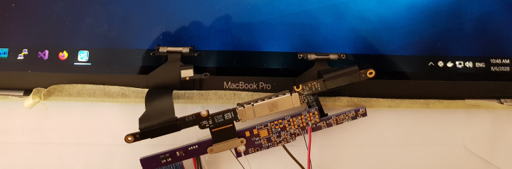 |
| Up and running (with external backlight power for now). |
No comments:
Post a Comment